The Chanute Multiple-winged Machine -The 'Katydid'
The multiple-winged glider, eventually dubbed the 'Katydid' by the experimenters,
went through many changes in the two weeks that it was flown at Miller beach. Perhaps
the best description of those changes and the flights themselves was written the
following year in 'Gliding Experiments' - a lecture by Chanute that was published
in the Journal of the Society of Western Engineers. The section concerning the 'Katydid'
is here, and complete lecture is on another page.
The images are presented here as thumbnail images.
Click on the image for a full size image.
After abandoning this first form of machine, the experimenters in the sand dunes
next tested the machine built after the fashion of the ladder kite which had proven
so steady in the air.
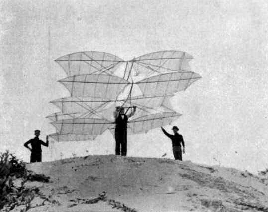
Fig. 224 exhibits a front view of this arrangement. It consisted of six pairs of
wings, superimposed and trussed together, pivoted at their roots upon a central
frame, the lower chord of which was spread open to receive the man at the center.
Here he was expected only to move for the purpose of steering, the stability to
be maintained by the movements of the wings above him, which swung on their pivots
back and forth, restrained by rubber springs, when the wind struck one side more
than the other, or changed the center of pressure fore and aft. It will be seen
that this is just the reverse of the first method tested, in which the man moved
and the wings remained fixed. This wing movement took place as expected, but it
was very soon found that there was an essential difference between the support from
the wind derived from the same arrangement when flown as a kite, at an angle of
incidence of 30 to 40 degrees,
| FIG. 224. First Form Multiple-Wing Machine.
|
|
and when flown as a gliding machine, at an angle with the wind of three or four
degrees, which is the most favorable for reducing the total resistance to a minimum.
It was found that at very acute angles the moving air was deflected downward by
the front wings, so that the support under all the following wings was greatly diminished,
and that the apparatus was inefficient when its surface was considered. This had
been expected, from prior experiments, and the frame had been designed so that the
grouping of the wings could be readily changed. Then began an interesting and instructive
evolution. The grouping of the wings was gradually changed, through six permutations,
each being guided by gliding flights and by releasing bits of featherdown in front
of the machine, and watching the paths of the air currents which swept past the
wings. The result of this evolution was to change greatly the outward appearance
of the apparatus while retaining the same general principle.
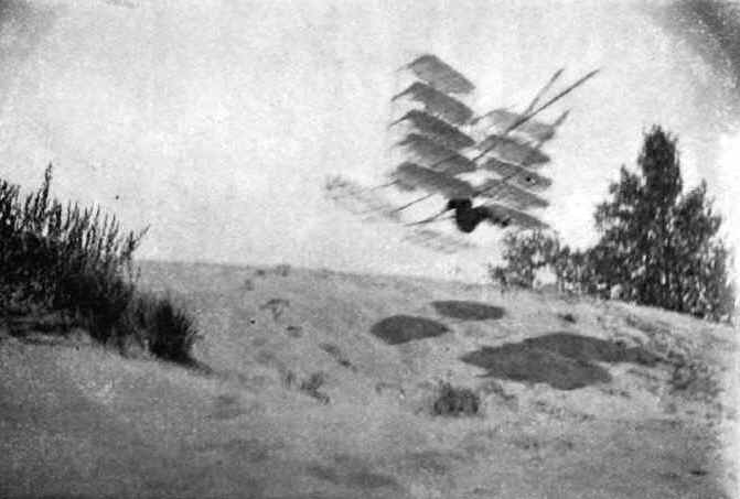
Fig. 225 shows the improved arrangement as seen from one side in flight. It will
be noticed that no less than five of the six pairs of wings have been superimposed
at the front, and trussed together. That the operator is within and under them,
and that a single pair of wings remains at the rear to serve as a tail. This tail
was flexible and vibrated up all down in flight when the angle of incidence varied
in consequence of the back and forth movements of the pivoted front wings.
| FIG. 225. Sixth Form Multiple-Wing Machine.
|
|
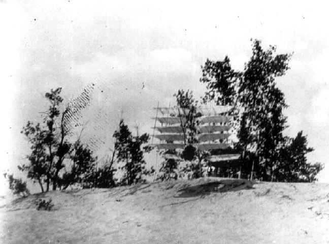
Fig. 226 shows a front view of the same machine in flight. About two hundred glides
were made, in winds of 13 to 22 miles an hour, on a descending course of about 1
in 4 (14o), the longest flight being 82 feet from a height of about 20
feet. There was, however, undue friction in the wing pivots, thus retarding their
| FIG. 226. Front View Multiple-Wing Machine in Flight.
|
|
automatic action, so that the operator had to move two or three inches, as against
some 15 or 18 inches on the previous machine, and there being some further defects
in the spacing of the wings, both vertically and horizontally, it was determined
to rebuild the machine with the practical information thus obtained.
Camp was accordingly broken up early in July, with the conviction that more had
been learned during this two weeks of experiment with full-sized machines than had
previously been acquired during about seven years of theoretical study and experiments
with models. The equipment was returned to Chicago, where three machines were constructed,
and towards the end of August they were taken out to the wilderness of sand dunes,
north of Dune Park, about five miles from Miller.
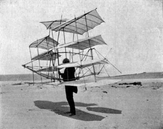
| FIG. 227. Seventh Form Multiple-Wing Machine.
|
|
Fig. 227 shows the multiple-wing machine as reconstructed. This consisted of the
same wings and of a new frame, and instead of ordinary pivots, there were ball bearings
at the ends of vertical wooden posts to which the roots of the wings were attached,
the latter being all trussed together, with vertical posts and diagonal wire ties,
this being probably the first application which has been made of the Pratt truss
to flying machine design. The frame was all made of spruce, the surfaces were of
Japanese silk varnished with pyroxelene; the complete machine weighed 33 1/2 pounds,
the supporting surface at the front was 143 1/2 square feet, including a concave
aerocurve over the top, added when the front wings were cut down to four pairs,
and the rear wings or tail measured 29 1/2 square feet in area. With this arrangement
a great many glides were made, with the result of more than doubling the lengths
previously attained, of reducing the angle of flight to 1 in 5, or 10o
to 11o, and of diminishing the required movements of the operator to
one or two inches in preserving the equilibrium.
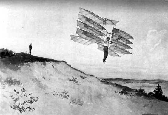
| FIG. 228. Multiple-Wing Machine in Flight.-(From a drawing.)
|
|
Fig. 228, reproduced from a drawing, shows this apparatus as it appeared in flight.
It might have been preferable to omit the aerocurve over the top, and to have placed
all the supporting surface in the pivoted wings at the front. This aerocurve was
added to save the expense of rebuilding the old wings, and this saving proved to
be a mistake. The wings were so far racked and distorted by their prior service
that they did not support alike and did not balance the weight properly, and thus
the results obtained with that machine were inferior to those to be hereafter described.
Yet the principles deemed to be sound, and it is believed that the apparatus can
be further improved.